- 您现在的位置:买卖IC网 > Sheet目录3887 > PIC16F84A-04E/SS (Microchip Technology)IC MCU CMOS 4MHZ 1K FLASH 20SSOP
2001 Microchip Technology Inc.
DS35007B-page 31
PIC16F84A
6.10.2
WDT PROGRAMMING
CONSIDERATIONS
It should also be taken into account that under worst
case conditions (VDD = Min., Temperature = Max., Max.
WDT Prescaler), it may take several seconds before a
WDT time-out occurs.
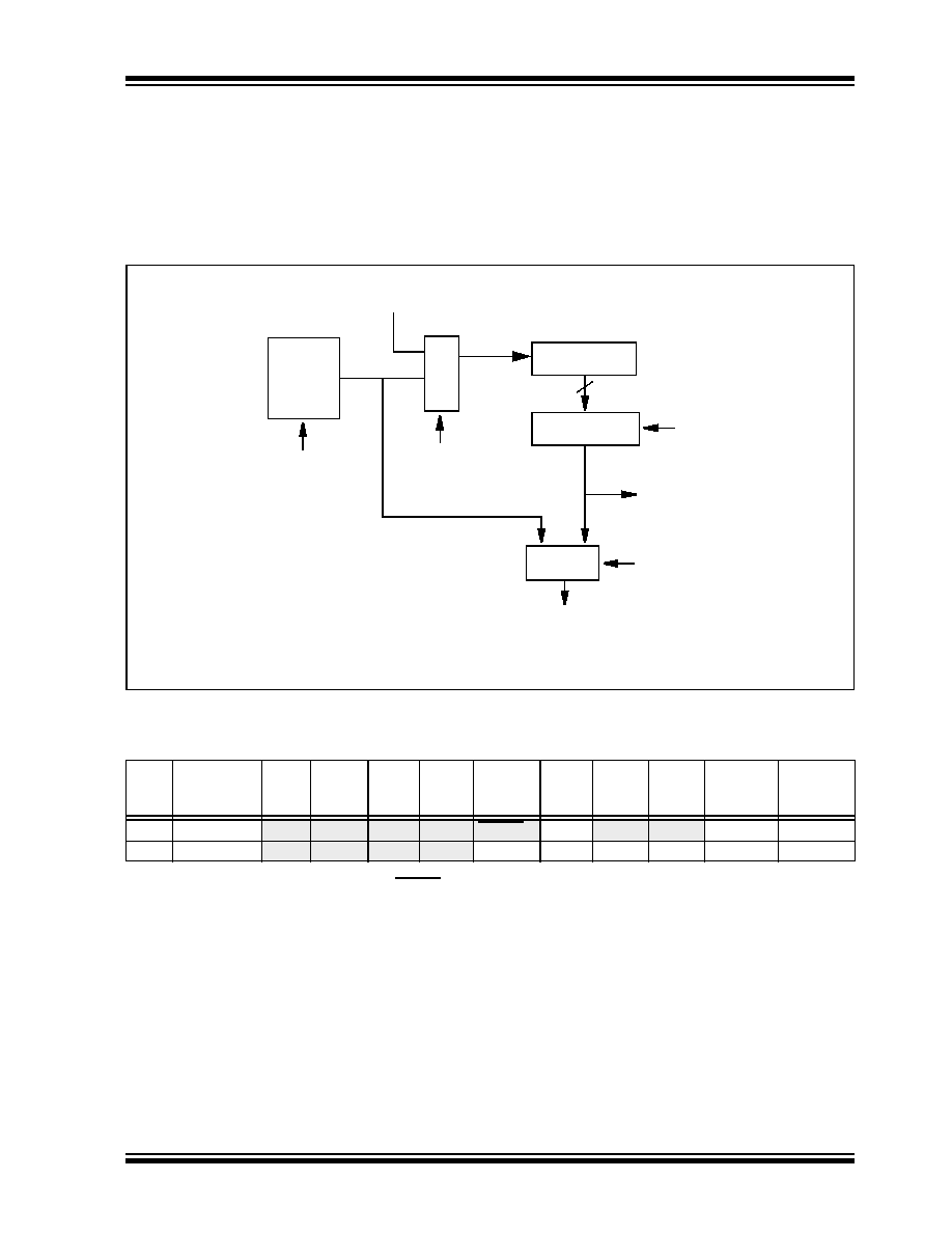
FIGURE 6-11:
WATCHDOG TIMER BLOCK DIAGRAM
TABLE 6-7:
SUMMARY OF REGISTERS ASSOCIATED WITH THE WATCHDOG TIMER
From TMR0 Clock Source
To TMR0 (Figure 5-2)
Postscaler
WDT Timer
M
U
X
PSA
8 - to -1 MUX
PSA
WDT
Time-out
1
0
1
WDT
Enable Bit
PS2:PS0
8
MUX
Note:
PSA and PS2:PS0 are bits in the OPTION_REG register.
Addr
Name
Bit 7
Bit 6
Bit 5
Bit 4
Bit 3
Bit 2
Bit 1
Bit 0
Value on
Power-on
Reset
Value on all
other
RESETS
2007h
Config. bits
(2)
PWRTE(1)
WDTE
FOSC1
FOSC0
(2)
81h
OPTION_REG
RBPU
INTEDG
T0CS
T0SE
PSA
PS2
PS1
PS0
1111 1111 1111 1111
Legend: x = unknown. Shaded cells are not used by the WDT.
Note
1: See Register 6-1 for operation of the PWRTE bit.
2: See Register 6-1 and Section 6.12 for operation of the code and data protection bits.
发布紧急采购,3分钟左右您将得到回复。
相关PDF资料
PIC16F84A-04E/SO
IC MCU CMOS 4MHZ 1K FLASH 18SOIC
PIC16F785-I/SS
IC PIC MCU FLASH 2KX14 20SSOP
PIC16C433T-I/SO
IC MCU CMOS 8BIT 10MHZ 2K 18SOIC
PIC16C773T-E/SO
IC MCU OTP 4KX14 A/D PWM 28SOIC
PIC16CE623T-30/SO
IC MCU OTP 512X14 EE COMP 18SOIC
PIC16F1825-E/ML
MCU PIC 14K FLASH 1K RAM 16QFN
PIC16F1828-I/SO
IC PIC MCU 8BIT 14KB FLSH 20SOIC
PIC16F688-I/SL
IC PIC MCU FLASH 4KX14 14SOIC
相关代理商/技术参数
PIC16F84A-04I/P
功能描述:8位微控制器 -MCU 1.75KB 68 RAM 13 I/O 4MHz Ind Temp PDIP18 RoHS:否 制造商:Silicon Labs 核心:8051 处理器系列:C8051F39x 数据总线宽度:8 bit 最大时钟频率:50 MHz 程序存储器大小:16 KB 数据 RAM 大小:1 KB 片上 ADC:Yes 工作电源电压:1.8 V to 3.6 V 工作温度范围:- 40 C to + 105 C 封装 / 箱体:QFN-20 安装风格:SMD/SMT
PIC16F84A-04I/P
制造商:Microchip Technology Inc 功能描述:IC 8BIT FLASH MCU 16F84 DIP18
PIC16F84A-04I/SO
功能描述:8位微控制器 -MCU 1.75KB 68 RAM 13 I/O 4MHz Ind Temp SOIC18 RoHS:否 制造商:Silicon Labs 核心:8051 处理器系列:C8051F39x 数据总线宽度:8 bit 最大时钟频率:50 MHz 程序存储器大小:16 KB 数据 RAM 大小:1 KB 片上 ADC:Yes 工作电源电压:1.8 V to 3.6 V 工作温度范围:- 40 C to + 105 C 封装 / 箱体:QFN-20 安装风格:SMD/SMT
PIC16F84A-04I/SO
制造商:Microchip Technology Inc 功能描述:8BIT FLASH MCU SMD 16F84 SOIC18
PIC16F84A-04I/SS
功能描述:8位微控制器 -MCU 1.75KB 68 RAM 13 I/O 4MHz IndTemp SSOP20 RoHS:否 制造商:Silicon Labs 核心:8051 处理器系列:C8051F39x 数据总线宽度:8 bit 最大时钟频率:50 MHz 程序存储器大小:16 KB 数据 RAM 大小:1 KB 片上 ADC:Yes 工作电源电压:1.8 V to 3.6 V 工作温度范围:- 40 C to + 105 C 封装 / 箱体:QFN-20 安装风格:SMD/SMT
PIC16F84A-04I/SS
制造商:Microchip Technology Inc 功能描述:8BIT FLASH MCU SMD 16F84 SSOP20
PIC16F84A-20/P
功能描述:8位微控制器 -MCU 1.75KB 68 RAM 13 I/O 20MHz PDIP18 RoHS:否 制造商:Silicon Labs 核心:8051 处理器系列:C8051F39x 数据总线宽度:8 bit 最大时钟频率:50 MHz 程序存储器大小:16 KB 数据 RAM 大小:1 KB 片上 ADC:Yes 工作电源电压:1.8 V to 3.6 V 工作温度范围:- 40 C to + 105 C 封装 / 箱体:QFN-20 安装风格:SMD/SMT
PIC16F84A-20/P
制造商:Microchip Technology Inc 功能描述:IC 8BIT FLASH MCU 16F84 DIP18